I prefer the GPS to be powered continuously. The older units required a considerable time to acquire satellites, so any time the bike is turned off (e.g. filling the tank), the GPS is then useless for a period. The Zumo 660 is much faster to acquire satellites, and its battery could mean that it would just continue with the ignition off. However, when the power is removed, it pops up a dialog saying that it will switch off in 30 seconds unless you tell it otherwise. I'm not likely to remember to do that, so I want its power to be constantly on.
The instrument panel contains a clock, so there is an always on source of power available there.
Next step is to remove the instrument panel. Perhaps not strictly necessary, but it does make life easier.
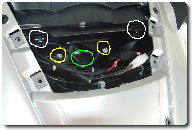
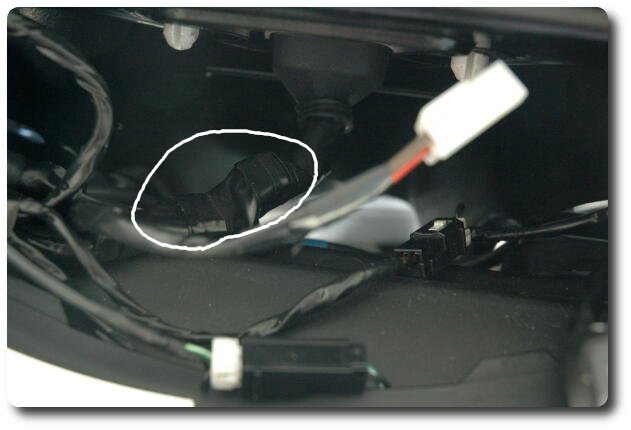
Remove the two clips (in white circles) and then work the instrument panel back towards the rear of the bike. It is a bit stiff! When it is free, remove the cable. Pull the rubber boot away from the panel, the unclip the connector. NOTE: there is a retaining clip on the plug, located on one of the long sides. Pressing the long sides of the plug together will release the clip allowing the plug to be pulled off the socket in the instrument panel.
There are 2 conductors in this cable to which connections are made. Start by unwinding the electrical tape from the connector end. I went to the junction with other cables. You will see a purple wire and a black wire on the left hand side (looking from the front, with the connector in the same position as when plugged in.)
The purple wire is positive, and the black wire is negative. The purple wire is always energised. Note that the Sprint GT and ST share many components, but the wiring harness is not one of them. These colours may be different on an ST; and I believe the ST has a socket for a GPS to be connected.
|
|
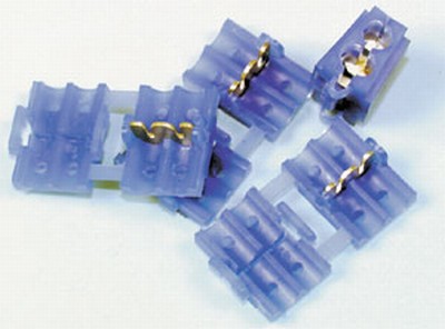
The items on the left are what I used to tap into the wiring. They are contact connectors and I bought them from Jaycar in Australia, an electronic component retailer. They may also be available from automotive stores. They should be readily available. The main benefit is that no cutting or soldering is required. Place the existing purple (black) wire into one side of the metal piece, and red (black) wire from the cable made up at the beginning in the other side. Fold over, and squeeze the connector with pliers and the connection is done.
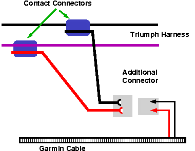
The right hand side is a pictorial wiring diagram. The Additional Connector may be any standard automotive type. The current rating is not too important. The Garmin cable is fused (left in) at 1 or 2 amps, and there is a 10 or 20 amp fuse for the instrument panel supply. The additional connector is to make it easy to disconnect and/or remove and/or change the GPS wiring in future. The cable from the GPS mount could be fed directly into the contact connectors but they are a one time use item.
The steps in this operation are as follows:
At this stage, I used a multimeter to verify that the red wire was positive. This requires temporarily reconnecting the battery. If you do this test, ensure the GPS is NOT installed.
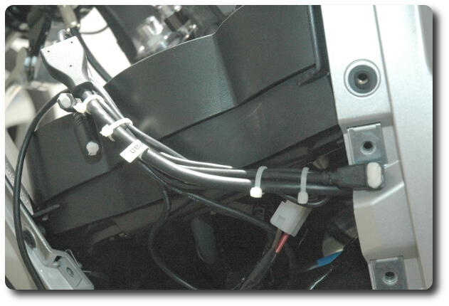
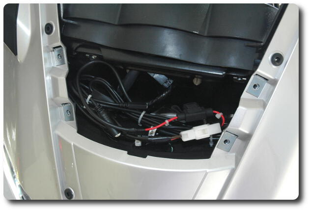
The cable from the Garmin mount needs to be routed from the triple clamp to in front of the instrument panel. There's an obvious route to follow. Run the cable over to the left side (rider's perspective) and cable tie to the cables from the left clip on. There's a clip around the left fork tube; remove it, feed the Garmin cable underneath and replace it on the fork tube. Follow the existing wires to the left fairing, secure with cable ties, and continue up towards the instrument panel.
Assembly, being the reverse of disassembly, can now be done. But first connect the battery and make sure the GPS is receiving power.
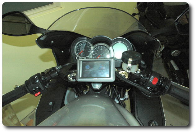
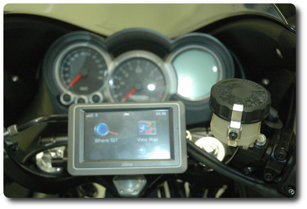
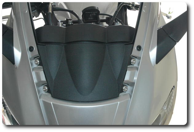
The above photos show how the finished installation looks. The lower photo was taken while sitting on the seat in standard riding position. It's an approximation to how it appears in normal use. The instruments are not blocked, and although not visible, there is no difficulty reaching the key in the ignition lock. My eyes have better depth of field than the lower photo - sorry for the blurry image, but it does show that the Zumo does not block the rider's view of the instrument panel.
And after a couple of hundred kilometres, I have no issues with the arrangement. But note that I do not like tank bags; with one of these you may want to consider the additional Extension Joint Assembly.
![]() Mounting Zumo 660 with GadgetGuy Hardware
Mounting Zumo 660 with GadgetGuy Hardware